

Submitted by Michael Bolton N5RLR
A QRP LIGHTBULB DUMMY LOAD
Here is a blast from the past. In radio lore, mention has been made of using lightbulbs as "dummy loads," or test loads, to check transmitters. The instruction manuals for the famed Heathkit tube-type Amateur Radio gear often specified using a common household lightbulb to test its 40-to-100-watt transmitters after kit construction. Lower-power QRP (5 watts or less) transmitters unfortunately don't have the energy output to properly utilize such a bulb. However, there is one that fits the bill: The #47 pilot-lamp bulb. Specified as 6.3VDC, 0.15A (150mA), the resistance (when lit) of the bulb filament calculates to be 42 ohms (6.3 / 0.15 = 42). This is close enough to our needed 50 ohms impedance to be of good use (1.19:1 VSWR).
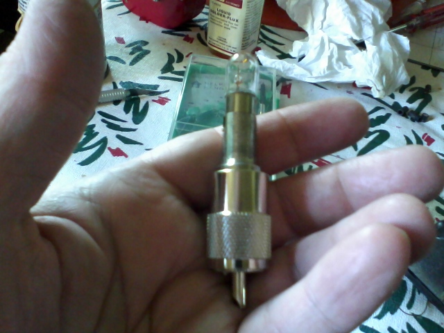
In the 1970s, Radio Shack and others offered for sale dummy loads consisting of #47 bulbs soldered to PL-259 plugs. These were compact of course, but had the drawback of the bulb having to be unsoldered to replace it in the event of damage or burnout. The version pictured here solves that problem by including a socket for the bulb to ease replacement.
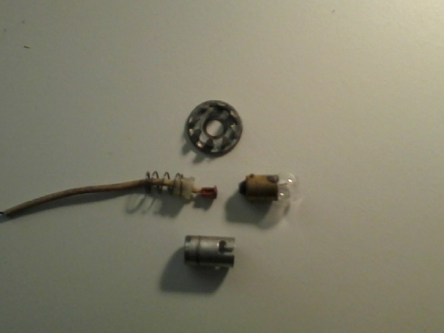
To build, the socket's inner insulator, wire pigtail, and spring are removed. After removing the coupling shell, he PL-259 connector body is held in a vise, and the ends of both the connector and lamp socket are scuffed with sandpaper or a Scotchbrite pad. Apply soldering flux to the mating surfaces, and place together. If needed, string a thin, stiff wire through the connector pin, hooking it over the ends of the pin and and the socket, to maintain alignment. Heat the socket/connector junction with a 100-to-150-watt soldering gun, and apply solder evenly around the circumference. Allow to cool naturally (this may take several minutes), and clean the junction with rubbing alcohol of any remaining flux.
Assemble the spring, pigtail and insulator, and bulb into the socket, threading the pigtail through the connector pin. Mark the end of the connector pin on the pigtail's insulation. Disassemble, trim and strip the pigtail just before the mark and after. Apply flux and tin the wire with solder. Reassemble and solder the pigtail to the connector pin. To protect the bulb, a colored vinyl cap can be installed (usually sold as a 3/8" bolt-thread protector cap at home-improvement or hardware stores).
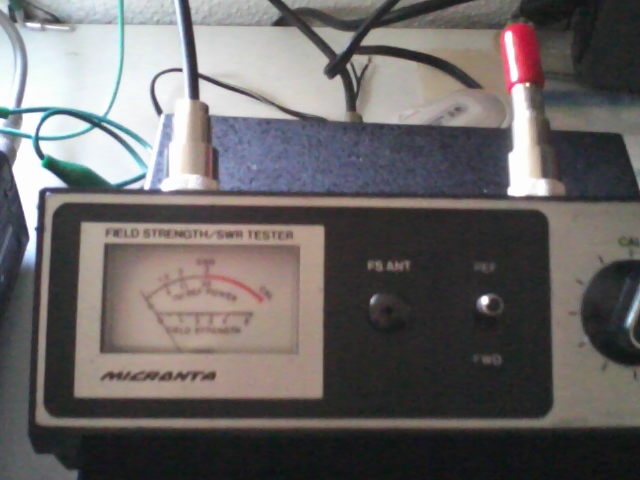
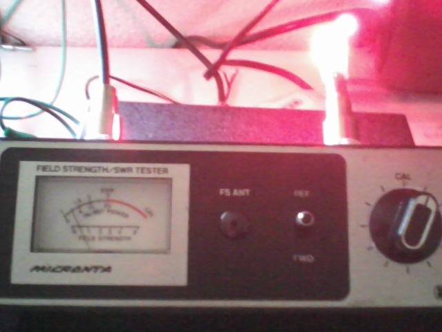
Connect to the output of a VSWR meter in place of an antenna, and verify operation. This particular bulb is known to handle up to 5 watts RF. Be careful when testing; transmit only long enough to make a particular adjustment or take a reading.